Rails Test
The Rails Test section allows service technicians to test the trolley locking and release mechanisms installed on each rail of the trolley depot.
A vending unit may contain multiple rails (trolley lanes).
Each rail contains its own mechanical and sensor components.
The test interface allows:
- selecting a specific rail
- monitoring sensors and actuators
- executing automated or manual tests
- diagnosing hardware faults
- verifying trolley detection and release mechanisms
Since all rails are identical in construction, the documentation demonstrates the testing process using Rail 1 as an example.
Rail Selection Page
Section titled “Rail Selection Page”The first page allows the technician to select which rail should be tested.
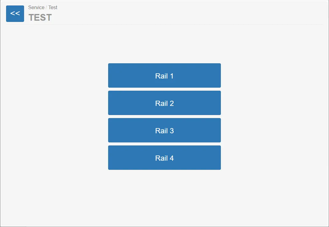
Available buttons:
- Rail 1
- Rail 2
- Rail 3
- Rail 4
Each button opens the testing interface for the selected rail.
Because all rails operate identically, the following documentation describes the testing process using Rail 1.
Rail Test Page (Example: Rail 1)
Section titled “Rail Test Page (Example: Rail 1)”The rail testing page displays the current state of the rail module and allows different test modes.
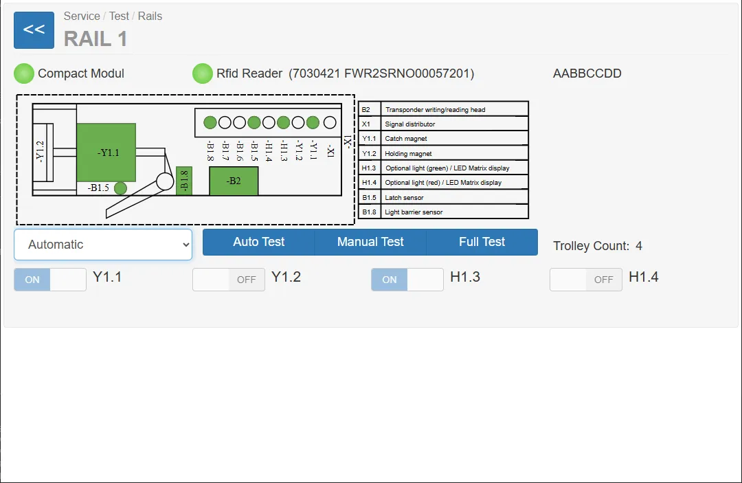
Main elements of the page:
- rail hardware diagram
- sensor indicators
- actuator controls
- RFID reader status
- rail operating mode
- automated and manual test functions
Hardware Status Indicators
Section titled “Hardware Status Indicators”Two main hardware modules are shown at the top of the page.
Compact Module
Section titled “Compact Module”This module contains the main electromechanical components of the rail system.
A green indicator means:
- the compact module is connected
- the controller communicates with the rail hardware
RFID Reader
Section titled “RFID Reader”An RFID reader may optionally be installed in the vending machine.
Purpose:
- identify trolleys equipped with RFID tags
- increase control over trolley movement
- prevent unauthorized trolley removal
- track trolley usage
Important:
The RFID reader is optional hardware.
Some machines may not include this module.
Hardware Diagram
Section titled “Hardware Diagram”The central graphic illustrates the rail hardware components and sensors.
Green elements in the diagram indicate active components or detected signals.
Operating Modes
Section titled “Operating Modes”The dropdown menu allows switching the rail controller into different test modes.
Test Types
Section titled “Test Types”Three types of tests are available.
Auto Test
Section titled “Auto Test”This test automatically verifies the functionality of the rail components.
Before starting the test the system displays a warning:
Ensure the locking area is clean and no trolley is present.
The system then performs several automated checks such as:
- signal light operation
- magnet activation
- sensor detection
While the test runs, the interface displays: Test running
When finished, the result dialog appears.
Example result:
Trolley Depot Simulator test OK
Manual Test
Section titled “Manual Test”The manual test allows the technician to perform step-by-step verification.
Steps:
- The system asks the technician to enter the number of trolleys.
- The test begins with guided instructions.
- The technician confirms the result of each step.
Example instructions:
- verify that the green light is active
- verify that both signal lights are active
- confirm sensor responses
The technician confirms each step by pressing OK or aborts using Cancel.
Full Test
Section titled “Full Test”The Full Test performs an extended diagnostic test of the rail.
This test combines Auto and Manual Tests and produces a detailed test report.
Test Results
Section titled “Test Results”When a test finishes, a result window displays the outcome.
Example:
Test 1: Green light works (OK) Test 2: Green and red lights work (OK) Test 3: Red light works (OK) Test 4: Lights off (not executed) Test 5.1: Trolley not removed (NA) Test 6.1: Trolley not inserted (NA)
The test result is saved as a CSV file on the system.
Example path: C:\var\RailTest.00001\Rail.1.2026-03-15T13-11-43.csv
These files can be used for diagnostics.